{"product":{"productId":"agid.27636","price":24.79,"name":"Clamping arm for hydraulic swing clamps, Form B"},"currency":"EUR"}
Description
Product description
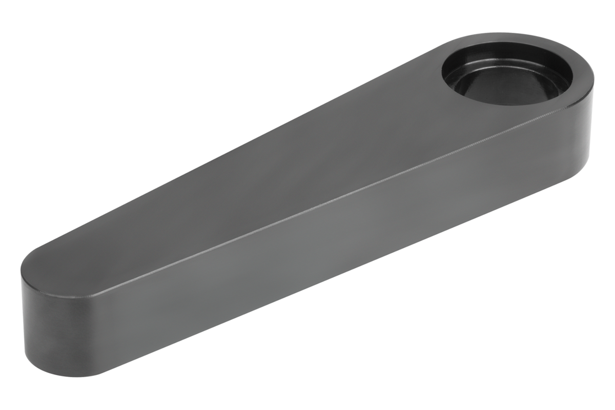
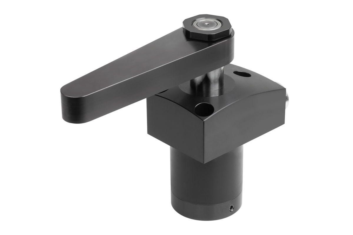
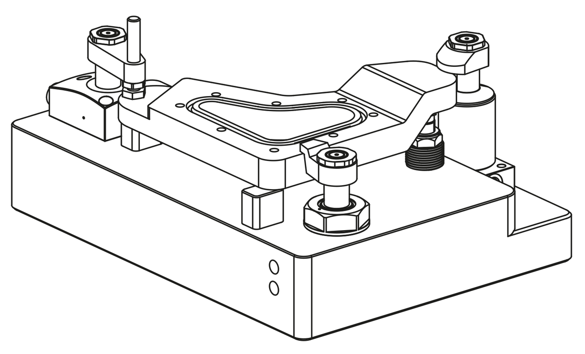
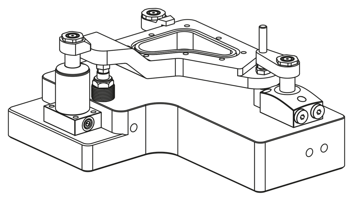
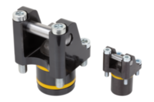
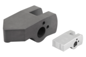
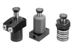
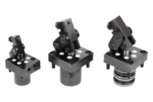
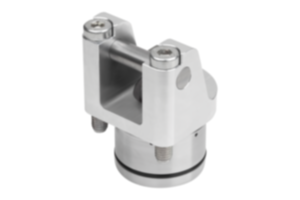
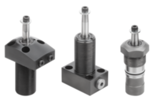
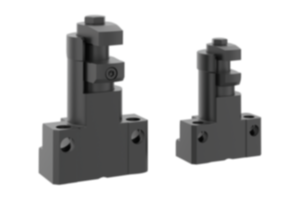
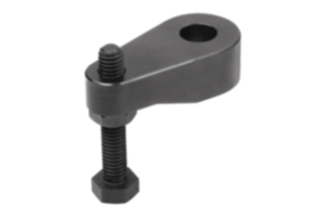
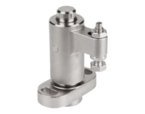
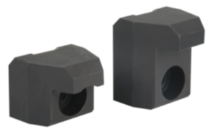
Single clamping arms for the swing clamp 04368-20. Different clamping situations can be realised with the different clamping arm designs. Fastening materials are supplied with the clamping arms.
Material
Steel.
Version
Black oxidised.
Note
Information on the clamping arm mountings as well as the effective clamping force depending on the operating pressure must be considered individually for each swing clamp.
The clamping force diagrams for the swing clamps are decisive for the dimensioning of the clamping arms.
The specified operating pressure must not be exceeded and must be adjusted if necessary.
The swivel movement of the clamping arms must not be hindered. The actual workpiece clamping process may only take place after the swing travel of the swing clamp is completed.
The thrust pieces should be so defined that contact with the workpiece only occurs after the swivel movement has been completed.
To prevent torques from being applied to the piston rod, the clamping arms must be held in place firmly during assembly.
Avoid encroachment in the swivel path. This could lead to pinching injury to the hands or other body parts.
Follow safety instructions.
Technical Data
- Max. operating pressure Form A and B: 200 bar.
- Max. operating pressure Form C: 500 bar.
- Max. operating pressure Form D: 300 bar.
- Max. operating pressure Form C: 500 bar.
- Max. operating pressure Form D: 300 bar.
Assembly
When mounting or removing the clamping arms, make sure that no torques are transmitted to the piston rod of the swing clamp. This can be prevented by holding the arm in place when tightening or loosening the fastening screw.
1. If the swing clamp is equipped with an overload protection, the first step is to check it by turning the piston until the overload protection can be felt to engage. A swing clamp has three engagement points at 120° intervals.
2. The installation of the clamping arms is normally carried out when the clamp is not under pressure. After the clamping arm is positioned on the piston rod, the screw or nut can be tightened. However, if an exact clamping position of the clamping arm is required, the piston of the swing clamp must be retracted under pressure. The clamping arm can then be mounted in the desired position.
3. After attaching the clamping arm, the clamping process of the swing clamp should be checked several times for correct clamping point and clamping travel.
4. After changing the clamping arm, the torque of the fastening screw should be checked again after a few clamping cycles and, if necessary, retightened.
On request
Other sizes and types.
Accessory
- Rest pads 02153.
- Self-aligning pads 02080, 02081, 02005, 02006.
- Gripper screws, hexagonal 07114.
- Self-aligning pads 02080, 02081, 02005, 02006.
- Gripper screws, hexagonal 07114.
Important note on downloading CAD models
In order to download our CAD models, you must log in first. If you have not created an account yet, please register under "My Account" (right side of the screen) and follow the instructions.
